Class C ,R160
Multi-jet Dry Type Vane Wheel Water Meter
It is a multi-jet super dry water meter for residentialÂ
application in sizes 15mm-20mm for cold  and hot meter.
Features
Compact design with smaller meter body.
Brass body is only 570g weight for save cost
45° inclined register, hot wire tamper proof.
Magnetic drive mechanism with anti-magnetic protection.
External regulation device
Standards ComplianceÂ
Directive 2004/22/EC on measuring instruments;Â
the European  Standard EN14154+A1+A2: Water Meter;Â
the International  Organization of Legal Metrology OIML R-49: 2006(E)
Optional FeaturesÂ
Several lengths and connections available on request
Non return Valve
Reed switch option
Working Conditions
Water temperature: ≤50ºC for cold water meter Â
                   ≤90ºC for  hot water meterÂ
Water pressure:   ≤1MPa or 1.6MPa optional
          (10bar or 16bar option)
Accessories
Each meter has one set coupling optional: 2pcs coupling, 2pcs coupling nuts and 2pcs washers.
Installation requirements
The meter should be installed in horizontal position with the direction of the flow asÂ
indicated by the arrow cast in the meter body with the register face upwards.
Pipeline must be flushed before installation.
The meter should be constantly full of water during operation.
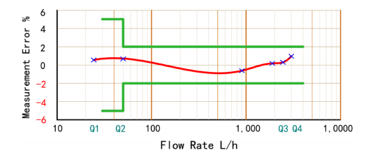
Maximum Permissible Error
In the lower zone from Qmin inclusive up to but excluding Qt is ±5%.
In the upper zone from Qt inclusive up to and including Qs is: cold water meter ±2%.

| DN(mm) | Â | 15 | 20 |
| Size(inch) | Â | 1/2" | 3/4" |
| Q4(m³/h) |  | 3.125 | 5 |
| Q3(m³/h) |  | 2.5 | 4 |
| R80 | Q2(l/h) | 50 | 80 |
| Â | Q1(l/h) | 31.25 | 50 |
| R100 | Q2(l/h) | 40 | 64 |
| Â | Q1(l/h) | 25 | 40 |
| Max.Reading (m³) | 9999 | ||
| Min.Reading (Liter) | 005 | ||
| Max.Pressure (bar) | 16 | ||
| Pressure Loss (ΔP) | 63 | ||
| Max.Temperature | T30 or T90 | ||
Â
Casing is a large-diameter pipe that serves as the structural retainer for the walls of oil and gas wells or wellbore.
It is inserted into a well bore and cemented in place to protect both subsurface formations and the wellbore from collapsing and to allow
drilling fluid to circulate and extraction to take place
The oil casing is a steel pipe used to support the well wall of oil and gas wells to ensure the normal operation of the whole well during drilling and after well completion. Several layers of casing shall be used for each well according to different drilling depth and geological conditions. Cement shall be used for cementing after casing is put into the well. It is different from TUBING and drill pipe and cannot be reused. It is a disposable consumable material. Therefore, casing consumption accounts for more than 70% of all oil well pipes.
Casing is a large-diameter pipe that serves as the structural retainer for the walls of oil and gas wells, or wellbore. It is inserted into a well bore and cemented in place to protect both subsurface formations and the wellbore from collapsing and to allow drilling fluid to circulate and extraction to take place.
Surface casing
- Protects the well from contamination in shallow water and gas layers.
- Supports the wellhead equipment and sustains the weight of the other layers of casing.
Intermediate casing
- Isolates different layers of pressure to facilitate normal circulation of drilling fluid and protect the production casing.
- Intermediate casing facilitates the installation of blow-out preventers, anti-leakage devices and tailpipes in the well.
Production casing (oil string)
- It is the conduit through which oil and gas pass from a below surface reservoir.
- It protects the well and separates fluids into various layers.
First, green pipes are threaded on each end. The threading is then inspected and, if necessary, rethreaded to ensure that the thread accurately connects to the coupling. The threading type includes STC/BTC/LTC. The casing pipes are strengthened by surface treatment and are subject to various inspections, including drifting and hydrostatic tests before they are coated and packaged into casing.
Casing pipes are ordinarily produced with outside diameter sizes of 114.3 mm to 508.0 mm.
Casing,Api 5Ct Casing,Api Spec 5Ct Casing PipeApi 5Ct Pipe Oil Casing
ESASTSUN OILFIELD EQUIPMENT MANUFACTURING (CAMBODIA) CO., LTD , https://www.eastsuncambodia.com