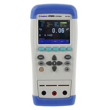
 It is understood that the bridge is used to measure a variety of tools, such as: resistance, inductance, capacitance and so on. The bridge is a circuit composed of four branches, so each branch is called the “arm†of the bridge. So what little knowledge about the bridge, the following simple to say.
 How to use a single-arm bridge:
1, first open the galvanometer lock (inside and outside), adjust the zero adjuster to zero.
2. Connect the measured resistance to the "" position.
Requires thicker, shorter connecting wires and scrapes the paint film. Tighten the connectors to avoid using clips. Poor connection of the connector will make the balance of the bridge unstable and may damage the galvanometer in severe cases.
3. Estimate the size of the resistance to be measured and select the appropriate bridge arm ratio so that the fourth gear of the comparison arm can be fully utilized. This makes it easy to balance the bridge and guarantees 4 significant digits of the measurement result.
4, first press the power button B, (lock) and then press the galvanometer button G (point).
5. Adjust the comparison arm resistance so that the galvanometer points to zero and the bridge is balanced. If the pointer indicates "+", the resistance of the comparison arm needs to be increased and the needle is pointed at "-", then the resistance of the comparison arm needs to be reduced.
6. Read data: Compare arm ratio arm = measured resistance 7. After the measurement is completed, disconnect the galvanometer button, disconnect the power button, and then remove the measured resistance, then lock the galvanometer lock. Damage to the galvanometer during handling.
The value of R2, R3, and R4 is adjusted by the bridge. When the bridge is balanced, R1 = R2 (R3/R4) and the measured resistance can be measured. From the figure we can see: R1 measured resistance includes the lead resistance and contact surface contact resistance, so the actual resistance should subtract lead resistance and contact surface contact resistance, the smaller the measured resistance, the greater the error of the lead, so the single arm The bridge is commonly used to measure the resistance of more than 1 euro, the general range is 1 ~ 99990 ohms. For the switch contact resistance is generally in the micro-European class, should not use this bridge, because the lead resistance is milliohm level, can not be measured, this time you can use dual-arm bridge.
Counter Current Closed Cooling Tower
A cooling tower is a device that uses water as a circulating coolant to absorb heat from a system and release it to the atmosphere to lower the water temperature.
Closed Cooling Tower has two operation modes.
Air cooling, air cooling + spraying.
The electronic control system actively stops the two switching modes according to the requirements of working conditions to save energy and reduce consumption.
Counter Current Closed Cooling Tower,Counter Current Cooling Tower,Countercurrent Cooling Tower, Cooling Tower For Sale
Wuxi Ark Fluid Science Technology Co., Ltd. , https://www.fangzhou-arkfluid.com